Dicaliant founder Dr Jaakko Juntunen has a quarter of a century background in RF EDA, and the last decade he has worked exclusively with antenna matching and optimization issues. With this background, Dicaliant is your competent partner for solving tricky impedance measurement and matching circuit simulation problems!
The Key toPerfect Matching
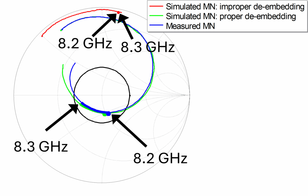
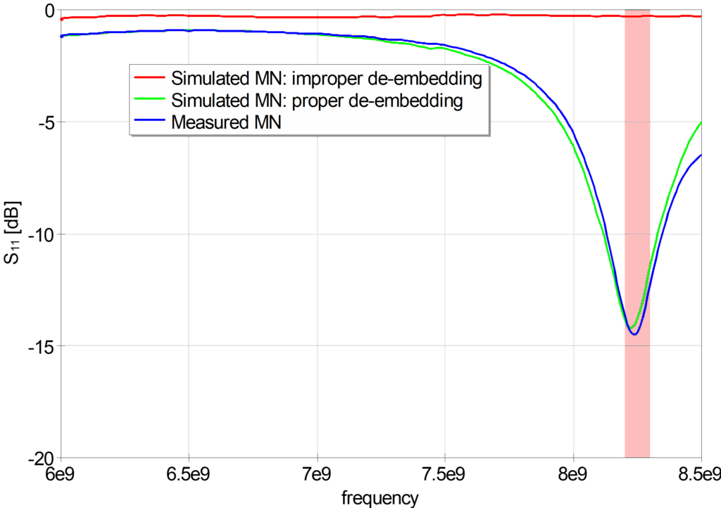
Over the years, Dr Juntunen discovered a repeating pattern in measured impedance data: the calibration was not good, or the reference plane was in wrong place. This makes matching simulations fail. With properly de-embedded measurements, the matching simulations are accurate.
Navigating the Challenges of Antenna Impedance in RF Design
Antennas are challenging, because their impedance depend upon use-case: different PCB material, housing, mounting, ground plane shape – all have an impact. Therefore antennas cannot be matched “in the factory” for all purposes, but a case-dependent matching network is required.
Tackling Calibration Challenges in Impedance Measurements
When impedance is measured at a specific point on the PCB, designers often employ “pigtails”, thin coaxial cables with exposed inner conductor extension in the other end. Pigtails can be precisely soldered on the PCB, but a key problem is how to calibrate or de-embed the pigtail itself.
So-called “port extension” is commonly applied at the VNA. It treats the pigtail as a uniform lossy transmission line, and de-embeds the respective model from the measurement. This usually works fine below 1 GHz and reasonably well at 2 GHz, but is inaccurate at higher frequencies. At 5 GHz, port extension is useless.
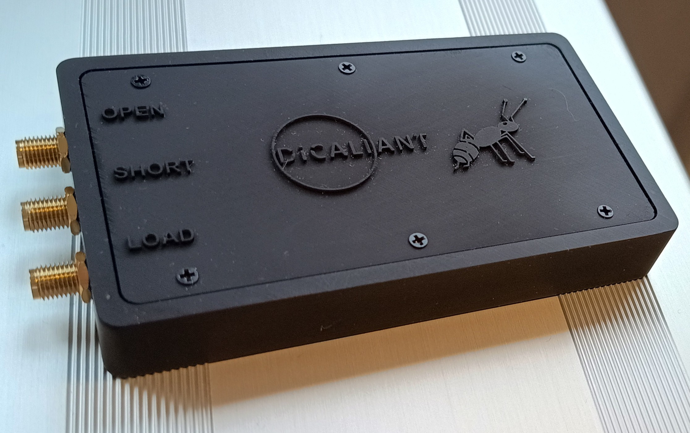
Enhancing Precision with Dicaliant Digital Twin Pigtails and Calibration Kits
Dicaliant has developed accurate de-embed models for pigtails, “Digital Twins”. These models take the discontinuities within pigtail into consideration, and move the reference plane precisely to the tip of the pigtail for all frequencies up to 8.5 GHz!