Our business is about making RF impedance measurement more reliable. This is for you, if you are familiar with Vector Network Analyzers and Smith chart, and want to measure impedance directly on PCB at 1.0 – 8.5 GHz.
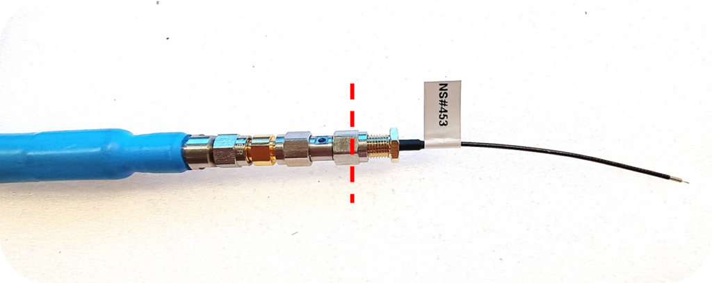
In such measurements, thin coaxial cables with unconnectorized other end are practical and commonly used. They are frequently called “pigtails”.
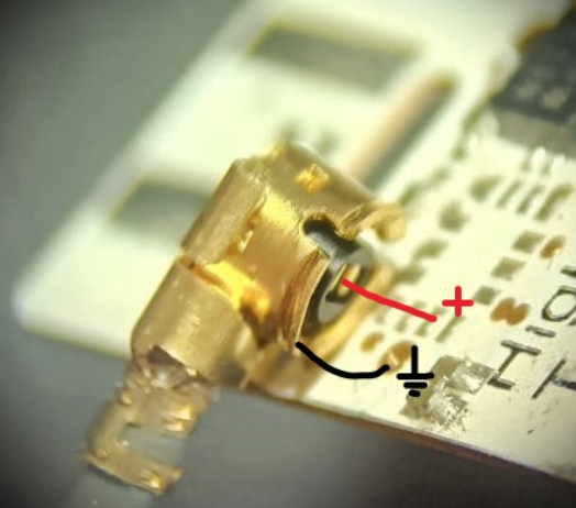
The problem we are solving relates to the calibration of measurements using pigtails. Regular VNA calibration kits provide accurate measurements, but the result is calibrated to the connector that mates with the connectors of the calibration kit, approximately denoted by red dashed line in the above picture.
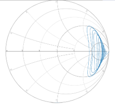
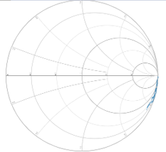
At several gigahertz frequencies this means that a pigtail rotates the pigtail tip impedance several rounds around Smith chart. If we measure open-ended pigtail, instead of an open-circuit response at 3 o’clock on the Smith chart, we see a result like this:
It hardly looks like an open circuit!
To overcome this problem, VNAs offer computational calibration plane translation which is often called “port extension”. In port extension, the measurement result is mathematically modified by applying a “negative” of a uniform transmission line model.
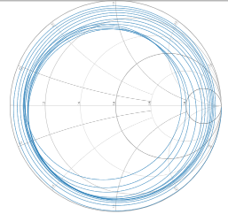
The process of applying a negative of a transmission model is generally called “de-embedding”. After applying port extension to open-ended pigtail measurement, we typically obtain a result that looks like a ball of yarn:
If we can’t measure open circuit impedance better than this, how can we expect our DUT impedance measurement be accurate?
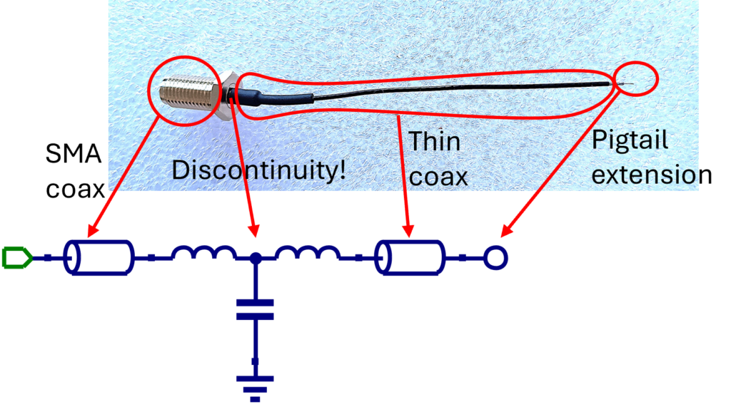
The clue is that the pigtail is not a uniform transmission line as assumed by port extension. It consists of four main parts:
Our work is to identify those four parts with our magic, and create a digital twin of any pigtail sample. This answers both questions made in the beginning: for us DDT is not a notorious pesticide but DDT =Dicaliant Digital Twin. Please check our publications and blogs for more detailed discussion on the model extraction.
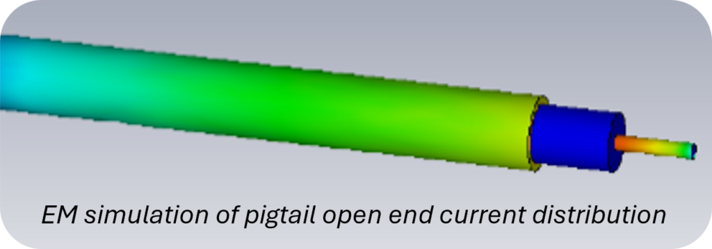
De-embedding DDT model moves the measurement reference to the tip of the pigtail, on the shell edge of the coaxial cable. If we measure open-ended pigtail, we only see the response of the pigtail extension. In fact, the open-ended extension radiates – thanks to currents fountaining on the outer surface of the coax shell.
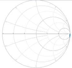
As an example, let’s look at the DDT de-embedding of the 150 mm long 8.5 GHz pigtail, whose bare response and port extension response were shown earlier. As expected, DDT de-embedding results in a little capacitive and radiating response, figure (a) below. If we cut off the pigtail extension along the shell edge, we get a nearly pure open circuit response as shown in figure (b) below.
(a) DDT de-embedding
(b) DDT de-embedding, pigtail cut at shell edge
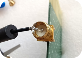
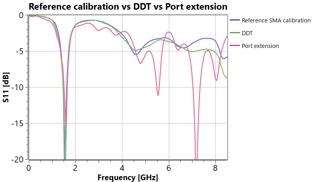
What happens if we measure less reactive impedance, like antenna? To have an accurate reference result, we first measured antenna response at SMA connector using conventional calibration. We then punched a pigtail through the SMA wall and connected the inner conductor to the SMA center pin, and soldered the pigtail shell to the SMA wall.
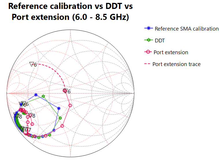
Then we measured the response at pigtail connector end, applied DDT and port extension, and compared the results with reference measurement. We see that above 2 GHz, port extension is getting unreliable, but DDT tracks the reference result consistently. Even more insight is given in the Smith chart plot, zoomed to 6.0 – 8.5 GHz. At 6 GHz, port extension is already 48 degrees in error, and above 6.7 GHz it goes entirely its own way.
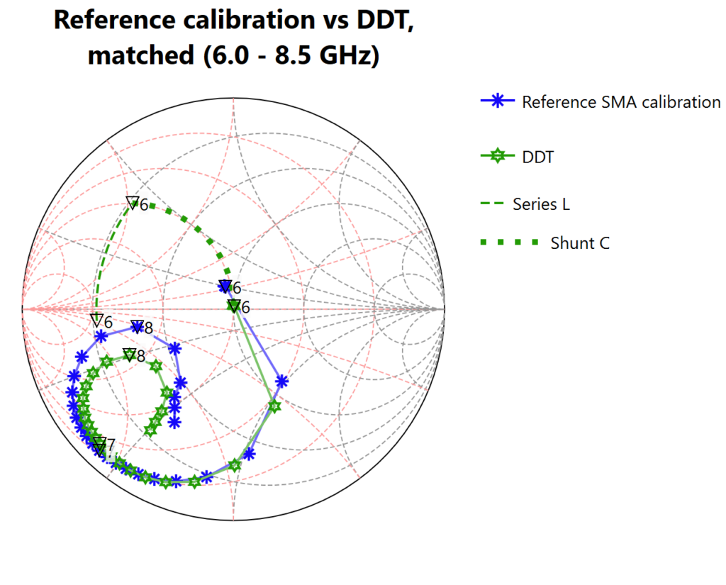
The phase error causes big problems in matching circuit design. For example, if we look at the admittance circles in the above Smith chart and obey 6 GHz marker, the port extension result suggests that the impedance can be matched by a single shunt capacitor, whose impedance transformation is depicted by dashed line ——- below. But if we look at the resulting correct impedance, a shunt capacitor would just transform an already small impedance a step closer to the short circuit. Thus relying on port extension would give entirely wrong matching suggestion.
In contrast, relying on DDT gives a correct matching suggestion (series-L shunt-C), therefore it is important that the measured S11 is accurate not only in magnitude but generally as a complex number in Smith chart.
If you read this far, you now have a good understanding about what we do, and how numerous Dicaliant customers are achieving accurate results with Dicaliant pigtails and DDT de-embed models. No connectors on PCB, just solder the pigtail on the signal trace, maybe put a few ferrites to block currents attempting to crawl along the pigtail shell, and there you are!
Order now pigtails with DDT models from our online shop, evaluation sets starting at 79€
About Us
When working with many customers over the years, Dicaliant founder Dr Jaakko Juntunen discovered a repeating pattern hampering productive use of simulators in real antenna matching: the impedance measurement reference plane was either poorly characterized or in wrong place. Or the available connectors were just inappropriate for the job 👉!
Pigtail cables allow precise and flexible positioning of the measurement point on board, without bulky connectors. Dicaliant pigtails are delivered with precise de-embed models providing accurate calibration reference at the open-ended tip of the cable.
Consultation Services
With 25+ years of expertise in solving thousands of RF and antenna simulation and modelling problems, we are enthusiastic to help you in your next challenge!
“I’ve recently had a breakthrough here at AntennaWare in modelling our antennas: thanks to your probes and reliable de-embedding I’ve been able to backfit our antenna model to the measurement using a very simple and robust approach. Dicaliant probes have been a life saver for me with the limited time I have to get things done.”
"Our main problem with our smart ring prototype radio interface was the miniature scale of the PCB,
causing almost hopeless measurement challenge of the antenna impedance that we had to match to
our BT chip's RF output. Thanks to Dicaliant's calibrated pigtails, we could accurately measure the
impedance directly at the chip pad and design the matching network with real data.
The result was exceptional RF performance in a tiny form factor."
"Dicaliant calibrated pigtails, used in conjunction with the ZAC-measurement process, have provided remarkable agreement between the simulated and measured performance of antenna matching circuits. We have achieved a first-time-right design in cases that would typically require 3-5 design iterations using a traditional approach. This speeds up our lab work and saves valuable prototypes."
We were designing a wideband antenna at 5-6 GHz, and discovered that SMA connector caused a big distortion to the measurement, making the matching of the antenna very difficult. But using Dicaliant pigtail calkit in the measurement, the problem was solved! We got the antenna matched quickly, and validated that the performance was as expected.”