
Welcome to our blog series exploring topics related to Dicaliant Ltd’s products and activities!
Dicaliant stands for Diagnosis and Calibration of Antenna Measurements. It was established to tackle the confusions around measuring antenna impedance, which is an enduring topic, despite automated instruments existing for decades. This confusion mainly relates to antennas on printed circuit boards (PCBs), either as off-the-shelf modules or as etched planar metallizations. It is especially relevant for antennas operating at frequencies where the PCB dimensions become a significant fraction of the wavelength, often starting around 3 GHz.
Where’s the confusion? It comes from connecting the device under test – the antenna – to a vector network analyzer (VNA). Mechanically, standard connectors like SMA are too large for fine PCB layouts, Figure 1. Electrically, these connectors act as long transmission lines, adding around 90 degrees to the measured phase at 3 GHz.
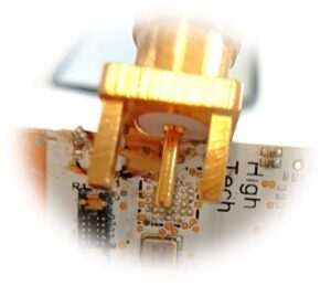
Figure 1. SMA connector appears bulky compared with tiny PCB layout details
To address this mechanical issue, engineers use pigtails—slim coaxial cables with an SMA connector on one end and an open-ended extension on the other (Figure 2). They are easy to solder onto PCBs, also when signal traces are small. Yet, pigtails seemingly exacerbate the electrical problem, prompting the design community to develop methods to compensate or de-embed their effects, such that the measurement result represents just the antenna impedance.

Figure 2. Pigtail is a practical way to connect VNA to signal trace on PCB
This raises questions: How should de-embedding be executed? Up to what frequency is it reliable? What if it isn’t? VNA vendors suggest using so-called port extension, which measures pigtail delay and mathematically adjusts the response. However, this works well only for uniform lines, which pigtails are not, due to mainly the discontinuity region between the SMA connector and the thin coax cable. As Figure 3 shows, results using port extension wobble at high frequencies. The response should be a dot at 3 o’clock in the Smith chart at all frequencies, so it is obvious that port extension method can only be used at relatively low frequencies.

Figure 3. Measured reflection coefficient S11 of an open-ended pigtail from 300 kHz to 8.5 GHz, after application of port extension on the VNA
While port extension suits measurements at ~1 GHz frequencies just fine, but what to do if our applications are 6 GHz WiFi or UWB? Unfortunately, even more parasitic problems than the pigtail discontinuity enter the stage when going higher in frequency.
Fortunately, Dicaliant offers calibration and de-embedding solutions extending to 8.5 GHz! There are more insights to follow in future blog posts. Stay informed!