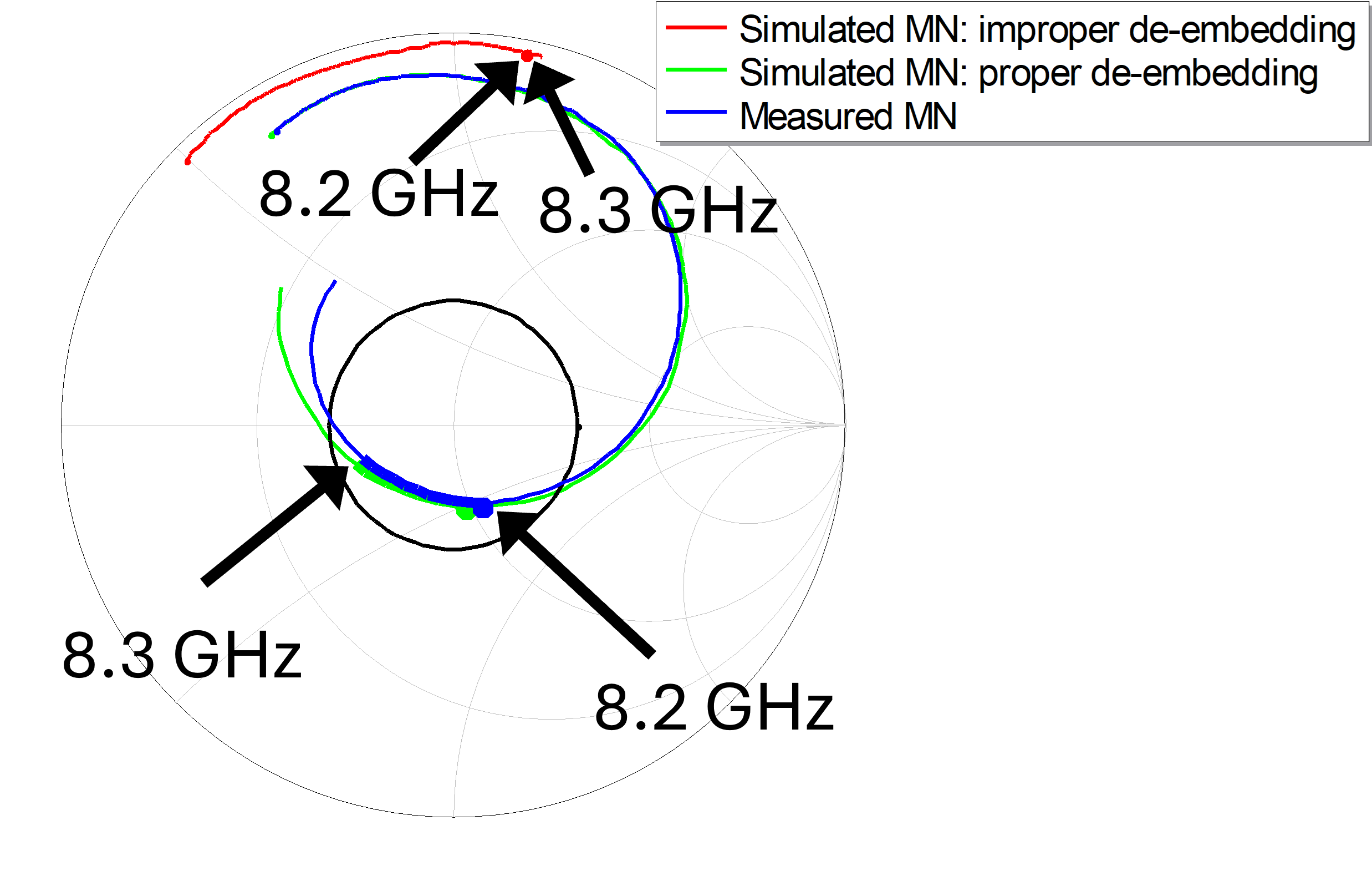
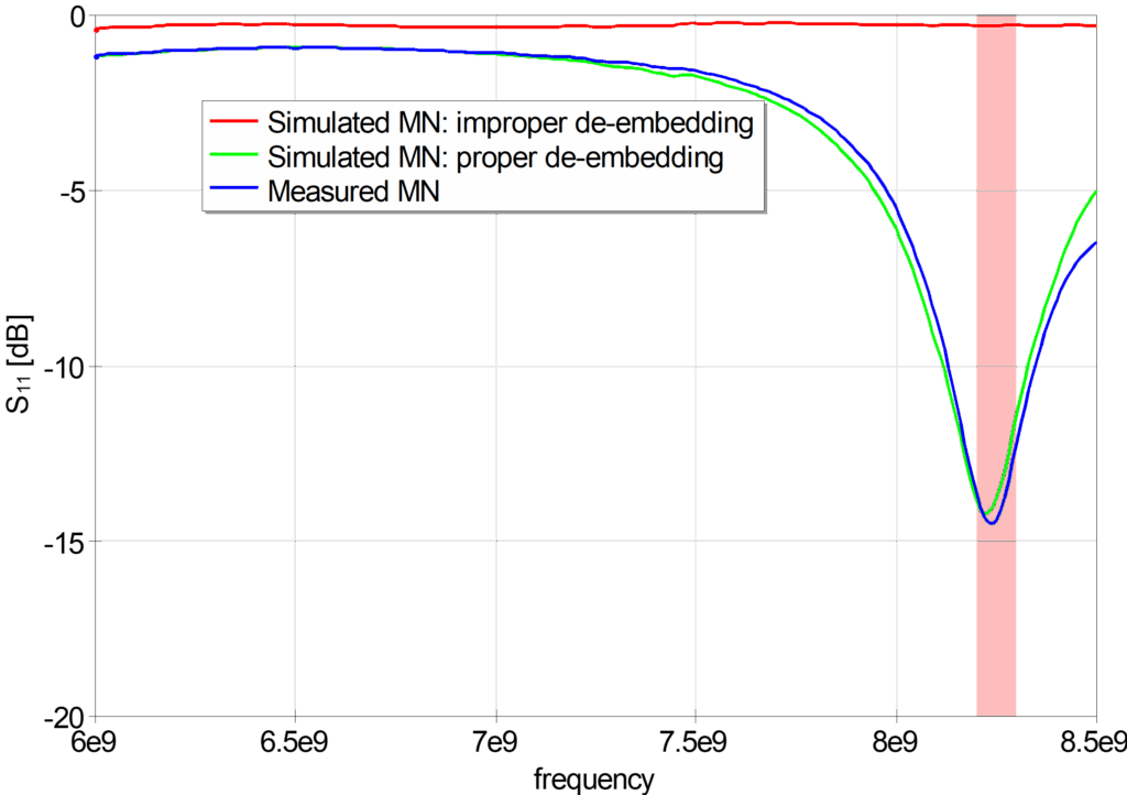
Dicaliant founder Dr Jaakko Juntunen has a quarter of a century background in RF EDA, working last decade specifically with antenna matching issues. Over the years, Dr Juntunen repeatedly encountered the same problem in measured impedance data: the calibration was done carelessly. Unfortunately, impedance matching is unforgiving regarding measurement phase reference accuracy.
This makes poorly calibrated measurements fail 👇. With proper de-embedding, the matching simulations are accurate.
Antennas are particularly challenging, because their impedance depend upon use-case: different PCB material, housing, mounting, ground plane shape – all have an impact. Therefore the same antenna requires a different matching network when used in a different product.
Calibration Kits and Digital Twin factory
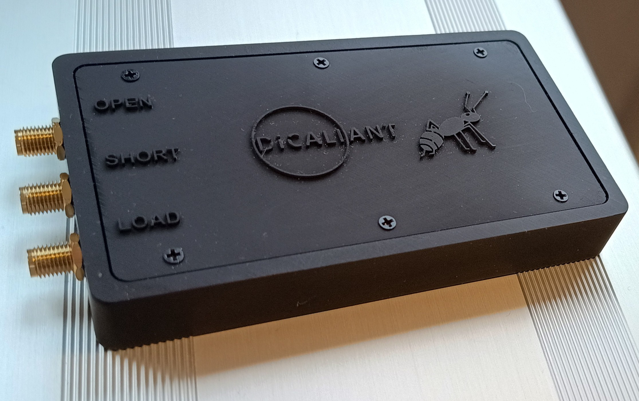
As a first Dicaliant product line, Dr. Juntunen developed a calibration kit for one-port measurements, to be used with pigtails that are specific to each kit.
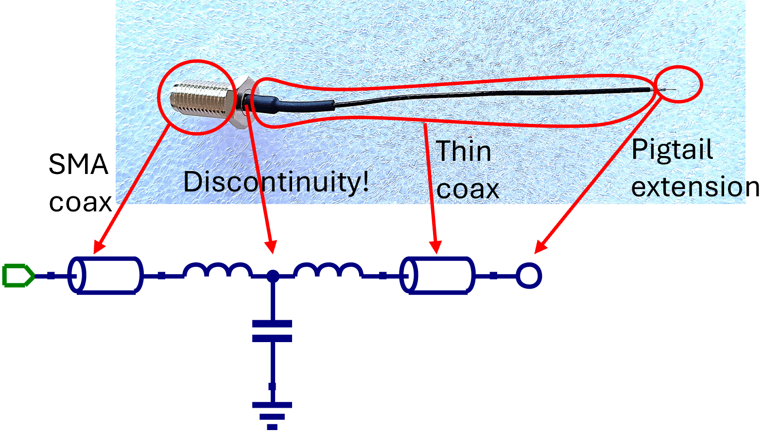
While these kits 👈 are still available, theoretical work and extensive testing resulted in a framework that allows synthesis of accurate de-embed models, or digital twins, of any pigtail. This methodology is pending two patents, and it marked the delivery of the DDT products – Dicaliant Digital Twin pigtails – as a lightweight calibration solution to on-board impedance measurement problem.
To bring the digital twin factory directly on your desk, a software product is in development allowing you to synthesize the de-embed model for your pigtail when you need it! Stay tuned for news!